• Confirmer la présence d’un ou plusieurs symptômes mentionnés dans le champ symptôme de ce bulletin technique.
• Vérifier l’état du filtre à huile.
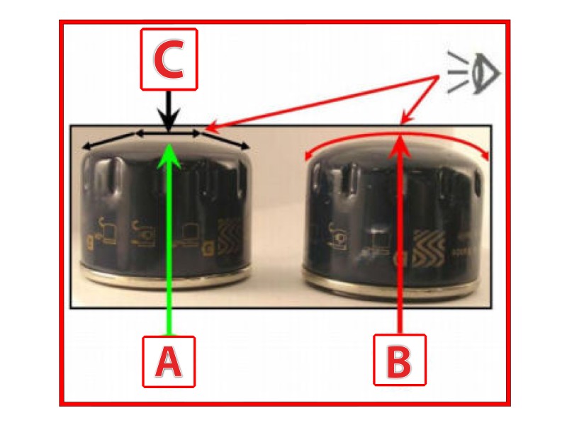
• Vérifiez visuellement que la partie supérieure du filtre à huile est ronde (voir image 1.A et 1.B).
S’il n’est pas possible de vérifier visuellement la conformité du filtre à huile :
• Placez le dessus (voir image 1.C) sur une surface plane.
• Vérifiez que le filtre à huile ne reste pas stable sur la face d’appui (voir image 1.C).
Si le niveau d’huile est supérieur au niveau minimum :
• Remplacez la pompe à huile par une neuve.
• Remplacez le filtre à huile.
• Effectuez un rinçage du moteur.
Si le niveau d’huile moteur est inférieur au minimum :
• Vérifiez l’état de la bielle et des roulements de vilebrequin.
• Remplacez le moteur et le turbocompresseur par un neuf, si la bielle ou les roulements du vilebrequin sont endommagés.
• Vérifiez l’état de l’arbre à cames, de l’arbre à cames et des capuchons d’arbre à cames, des cames et des poussoirs.
• Remplacez la culasse, le turbocompresseur, le filtre à huile, la pompe et le filtre à huile, si les roulements de bielle et le vilebrequin ne sont pas endommagés et si l’un des éléments de la vérification précédente est endommagé.
Si tous les éléments des vérifications ci-dessus sont corrects :
• Remplacez la pompe à huile par une neuve.
• Remplacez le filtre à huile.
• Effectuez un rinçage du moteur. |